Products
The "AT" post-tensioning anchorage system.
The TYROS "AT" type anchorage system has been designed considering the increasing needs of pre-stressing systems of the Global Construction Industry and manufactured with well proven materials while maximizing the cost effectiveness. Today pre-stressing technology has taken over the conventional methods used in building Bridges, Buildings, Metro rails, Flyovers, Tunnels, etc.
Choose by strand count.
Type codes read "strands AT strand class": 12 AT 15 is twelve 15.2 mm strands; 19 AT 13 is nineteen 12.7 mm strands. Hover a model to explode its full anchorage.
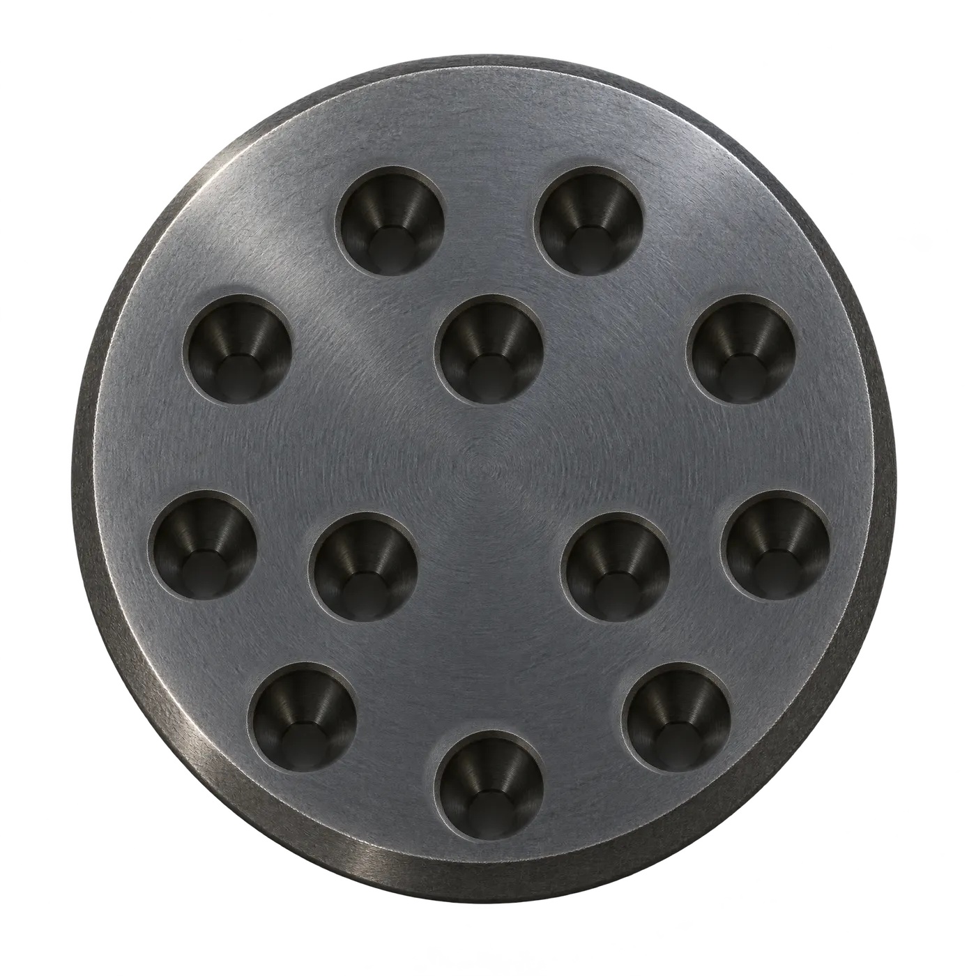
Hover to explode
12 AT 15
12 strands · Ø15.2 mm
12 AT 15
UTS 400 t · Jacking 320 t
12 AT 15
mm- A · Cone
- 245 × 245
- B · Min edge
- 200
- C · Spacing
- 300
- D · Pocket
- 62
- E · PCD
- 200
- Duct Ø
- 90
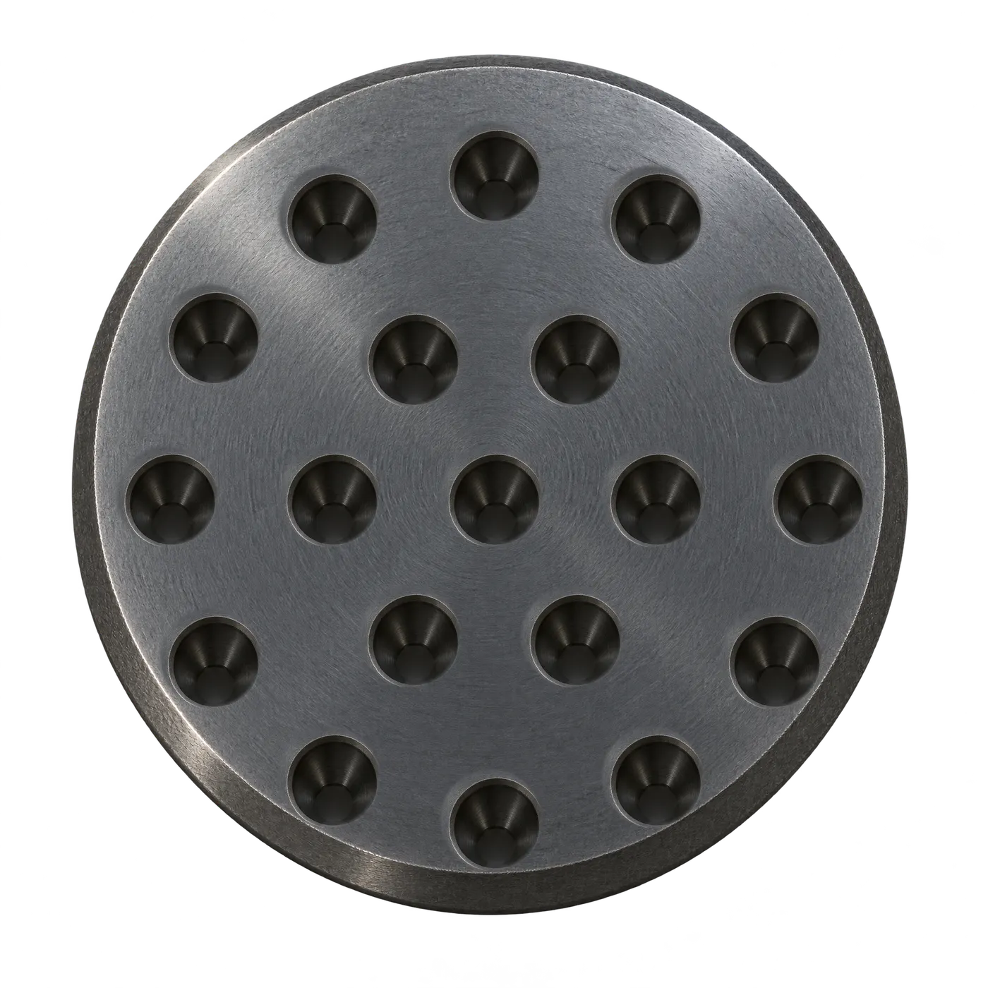
19 strands · Ø12.7 mm
19 AT 13
UTS 400 t · Jacking 320 t
19 AT 13
mm- A · Cone
- 245 × 245
- B · Min edge
- 198
- C · Spacing
- 325
- D · Pocket
- 62
- E · PCD
- 200
- Duct Ø
- 90
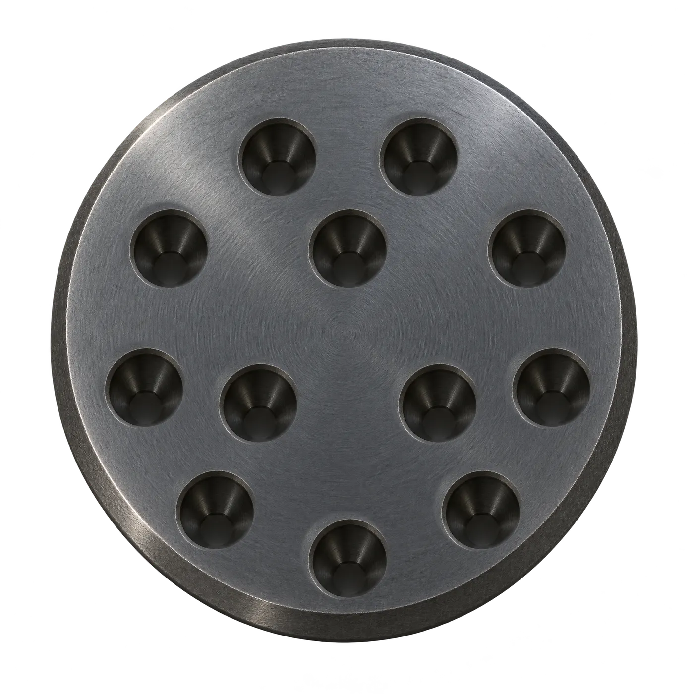
12 strands · Ø12.7 mm
12 AT 13
UTS 320 t · Jacking 256 t
12 AT 13
mm- A · Cone
- 207 × 207
- B · Min edge
- 148
- C · Spacing
- 260
- D · Pocket
- 52
- E · PCD
- 175
- Duct Ø
- 75
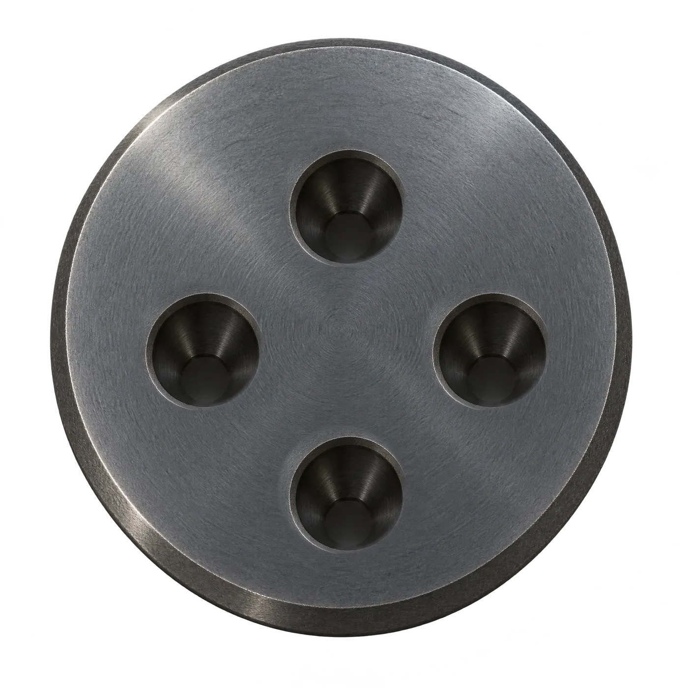
4 strands · Ø12.7 mm
4 AT 13
UTS 75 t · Jacking 60 t
4 AT 13
mm- A · Cone
- 145 × 145
- B · Min edge
- 120
- C · Spacing
- 220
- D · Pocket
- 45
- E · PCD
- 125
- Duct Ø
- 51
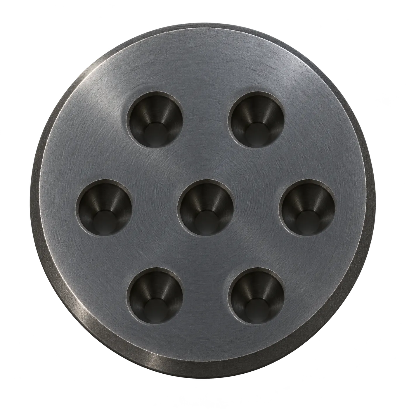
7 strands · Ø12.7 mm
7 AT 13
UTS 131 t · Jacking 105 t
7 AT 13
mm- A · Cone
- 145 × 145
- B · Min edge
- 120
- C · Spacing
- 220
- D · Pocket
- 45
- E · PCD
- 125
- Duct Ø
- 51
Scroll to rotate
Six parts. One load path.
Strand is by others. The five parts that turn 400 tons of strand force into concrete compression are all TYROS.
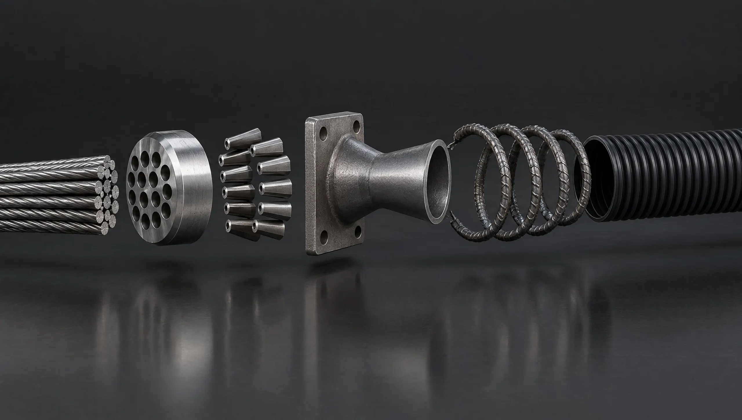
Strand
Carries the forceby others7-wire low-relaxation strand to IS 14268, 12.7 mm or 15.2 mm nominal. Threaded through the duct after concreting.
Anchor head
Holds every strandForged steel disc drilled with one conical hole per strand on a pitch circle (E). Bears on the cone flange and carries the whole tendon force.
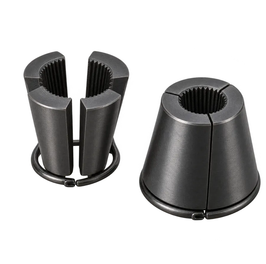
Wedges
Lock the strandThree-segment case-hardened wedges, one set per strand, held by a circlip. Serrated bore bites the strand as the jack releases.
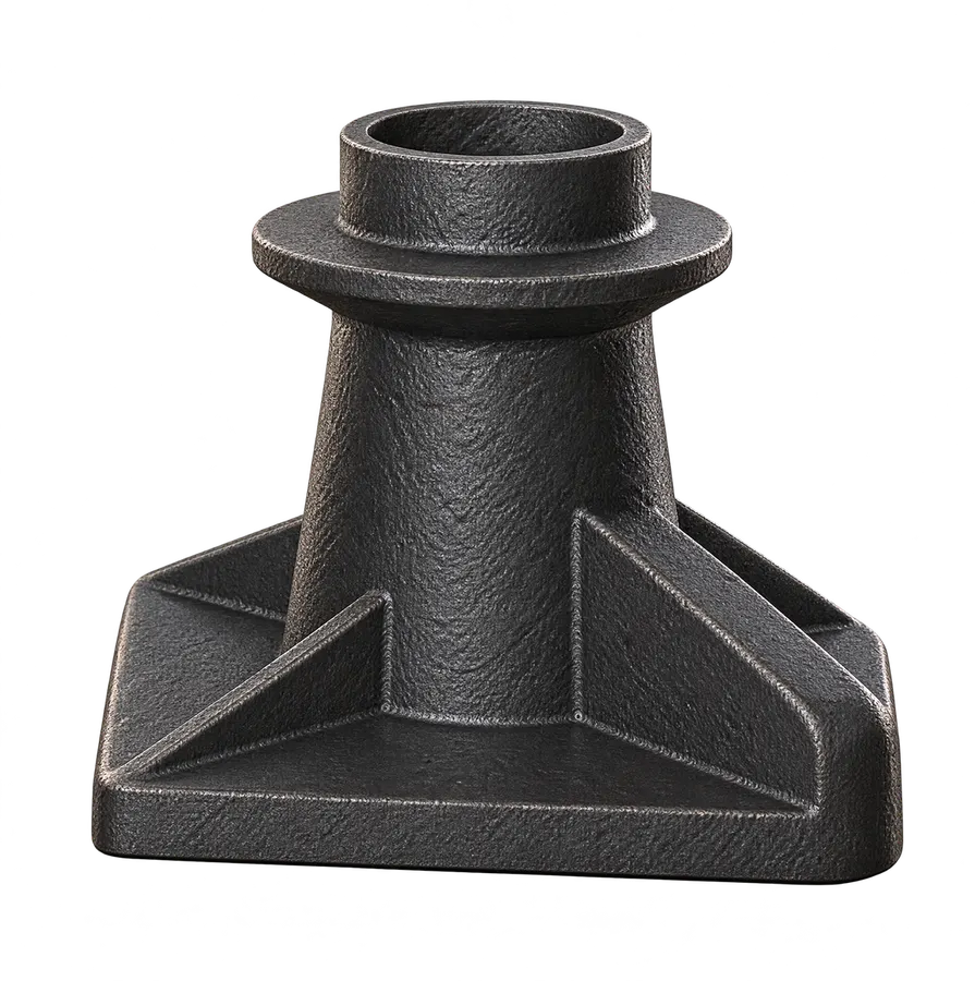
Anchor cone
Spreads the loadCast trumpet with a square bearing flange (A × A) and gusseted base. Turns a point load of up to 400 t into a bearing stress the concrete can take.
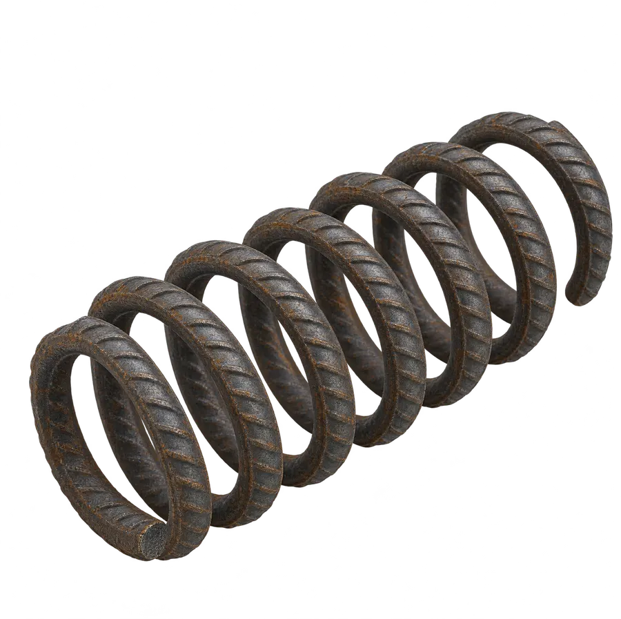
Spiral reinforcement
Confines the concreteHelical bar (H) of diameter F and length G, N turns at pitch J, cast around the cone to resist the bursting force behind the anchorage.
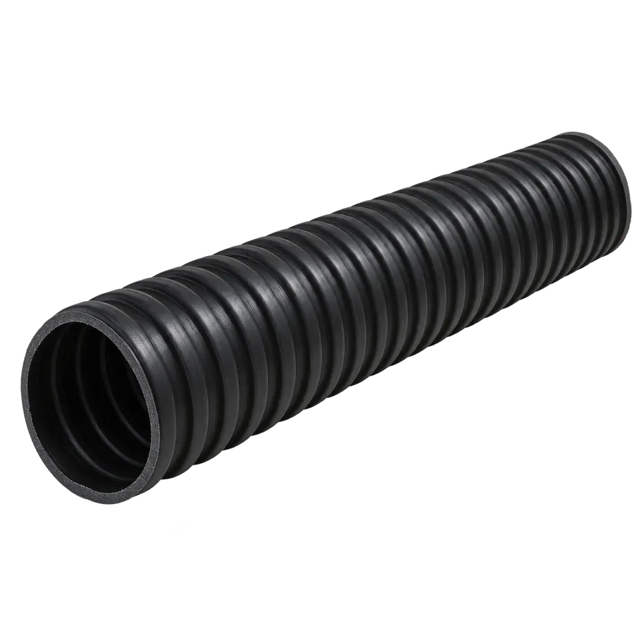
HDPE sheathing duct
Guides and protectsSingle-wall corrugated (SWC) high-density polyethylene duct sized to the cone. Holds the tendon profile, keeps concrete out and grout in.
Two wedges, two jobs.
Anchor wedges stay in the structure and are sized to the strand. Master wedges live in the jack and are built to be reused.
12.7 mm strand (AT 13 heads)
12.9 mm anchor wedge
- Segments
- 3-piece with circlip
- Material
- Case-hardened alloy steel (20MnCr5 / 20CrMnTi)
- Hardness
- Surface 58–62 HRC, tough core
Seats in the anchor head. One-time use, left in the structure.
15.2 mm strand (AT 15 heads)
15.2 mm anchor wedge
- Segments
- 3-piece with circlip
- Material
- Case-hardened alloy steel (20MnCr5 / 20CrMnTi)
- Hardness
- Surface 58–62 HRC, tough core
Seats in the anchor head. One-time use, left in the structure.
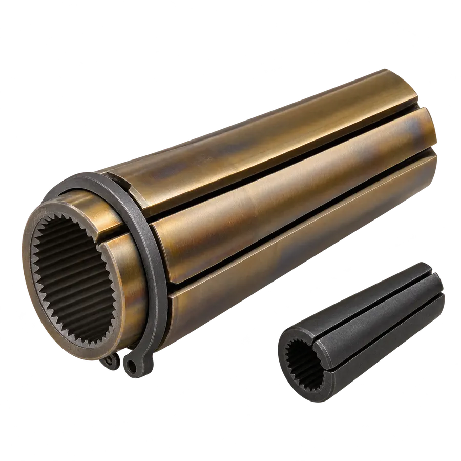
12.9 mm and 15.2 mm
Master wedge
- Segments
- 3-piece with circlip
- Material
- Through-hardened EN36 / 20MnCr5 nickel-chrome steel
- Hardness
- 58–60 HRC through, longer body
Sits in the jack's gripper, not the structure. Larger and longer so it survives hundreds of stressing cycles; replaced when the teeth wear.
HDPE sheathing duct for every cone.
Single-wall corrugated polyethylene duct, one size per cone diameter, so the tendon profile holds and the grout stays where it belongs.
- Single-wall corrugated HDPE to IRC:112 and MORTH §1800; corrugation gives bond and bending stiffness for the tendon profile.
- Supplied in 6 m lengths with push-fit couplers, grout vents and end sealing tape.
- Duct ID per the TYROS data sheet: 51 mm (4 & 7 strand), 75 mm (12 AT 13), 90 mm (12 AT 15 & 19 AT 13).
| Duct | ID / OD mm | Wall mm | Fits |
|---|---|---|---|
| SWC 51/63 | 51 / 63 | 2.3–3.0 | 4 AT 13 · 7 AT 13 |
| SWC 76/90 | 76 / 90 | 2.5–3.0 | 12 AT 13 |
| SWC 90/106 | 90 / 106 | 3.0–3.5 | 12 AT 15 · 19 AT 13 |
What ships with each model.
One line per anchorage. Strand is by others; everything else is TYROS.
| Model | Anchor head | Wedges | Anchor cone | Spiral reinforcement | HDPE sheathing duct |
|---|---|---|---|---|---|
| 12 AT 15 | 12-hole head, PCD 200 mm | 12 × 15.2 mm anchor wedge | Cone 245 × 245 mm, pocket 62 mm | Ø250 × 540 mm, 16 mm bar, 9 turns @ 60 mm | SWC 90/106 HDPE duct (ID 90 mm) |
| 19 AT 13 | 19-hole head, PCD 200 mm | 19 × 12.9 mm anchor wedge | Cone 245 × 245 mm, pocket 62 mm | Ø250 × 540 mm, 16 mm bar, 9 turns @ 60 mm | SWC 90/106 HDPE duct (ID 90 mm) |
| 12 AT 13 | 12-hole head, PCD 175 mm | 12 × 12.9 mm anchor wedge | Cone 207 × 207 mm, pocket 52 mm | Ø190 × 480 mm, 16 mm bar, 8 turns @ 60 mm | SWC 76/90 HDPE duct (ID 76 mm) |
| 4 AT 13 | 4-hole head, PCD 125 mm | 4 × 12.9 mm anchor wedge | Cone 145 × 145 mm, pocket 45 mm | Ø150 × 240 mm, 16 mm bar, 6 turns @ 40 mm | SWC 51/63 HDPE duct (ID 51 mm) |
| 7 AT 13 | 7-hole head, PCD 125 mm | 7 × 12.9 mm anchor wedge | Cone 145 × 145 mm, pocket 45 mm | Ø150 × 240 mm, 16 mm bar, 6 turns @ 40 mm | SWC 51/63 HDPE duct (ID 51 mm) |
01 · On site
A girder, ready to be stressed.
A live TYROS site. The girder's end face carries the anchorages; the jacks on the gantry above will pull every tendon to 80% of its strength.
Send us the tendon schedule. We'll send back the anchorage.
Anchorage specifications, anti-burst reinforcement details and the stressing methodology — for every contractor, on every job.
Need the tendons stressed too? See our post-tensioning stressing services.