Crash course
How a bridge is built.
Seven stages from the first pile to the first car. Three of them are where post-tensioning happens, and that is where TYROS works.
01
Foundations
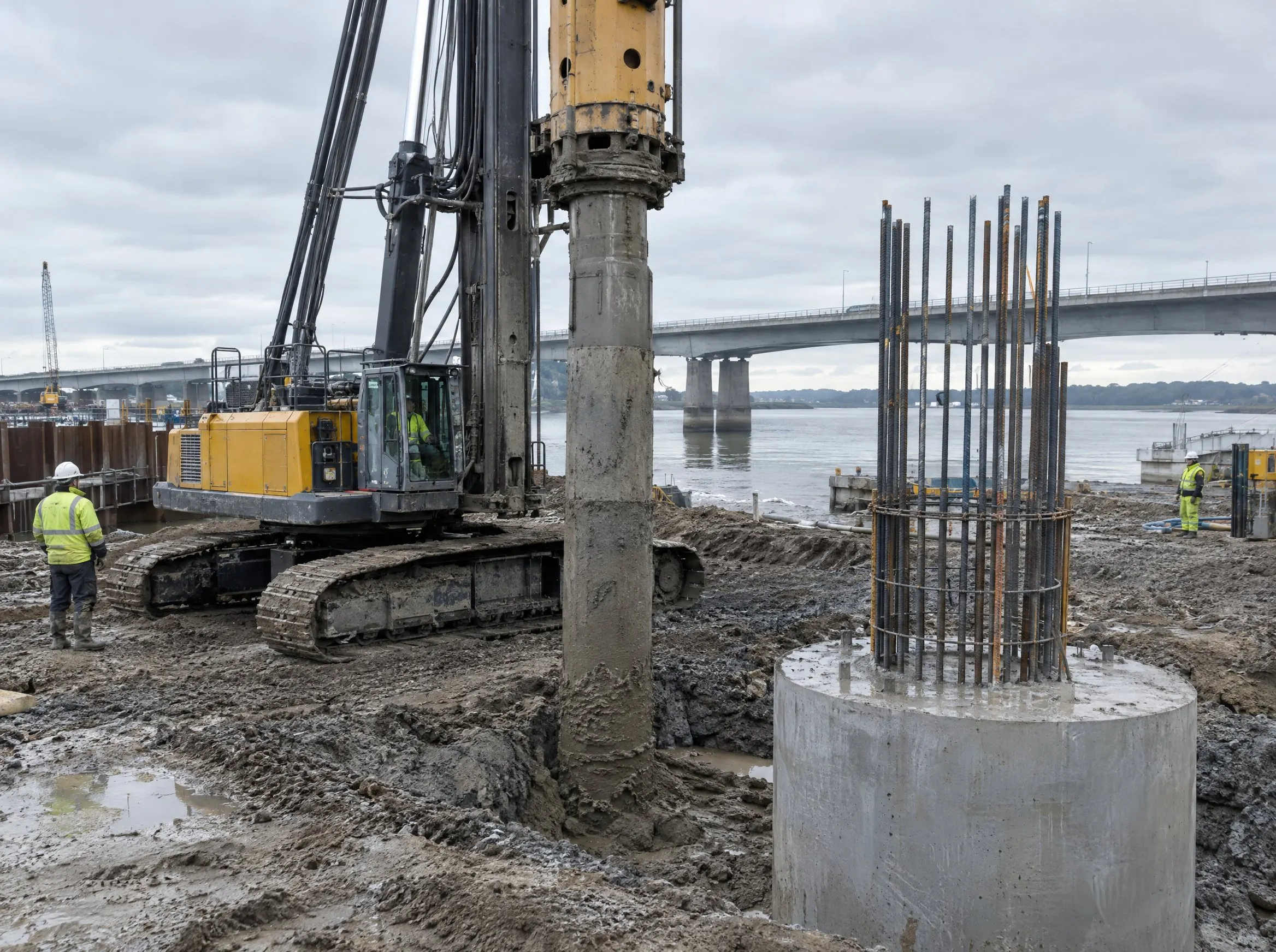
Piles and pile caps carry the whole bridge into the ground.
Bored piles, typically 1.0 to 1.5 m in diameter, are drilled to rock or firm strata and concreted in place. A pile cap ties a group of piles together so the pier above sits on all of them.
- Pile depth set by soil investigation, often 20–40 m
- Pile integrity tested before the cap is cast
- Pile cap reinforcement is the heaviest on the job
Other contractors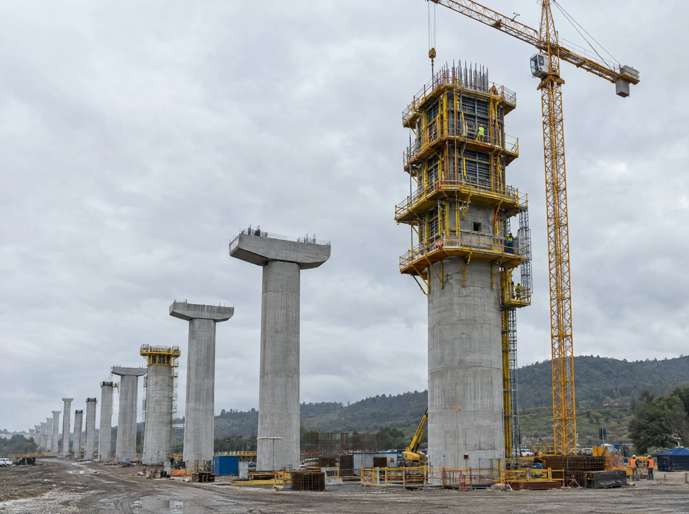
02
Piers
Columns rise from the pile caps to deck level.
Piers are cast in lifts with climbing or slip formwork. Their height sets the deck's clearance over roads, rail or water; their slenderness is what makes the bridge look light.
- Cast in 3–5 m lifts
- Verticality checked every lift
- Single-column piers keep the footprint small in cities
Other contractors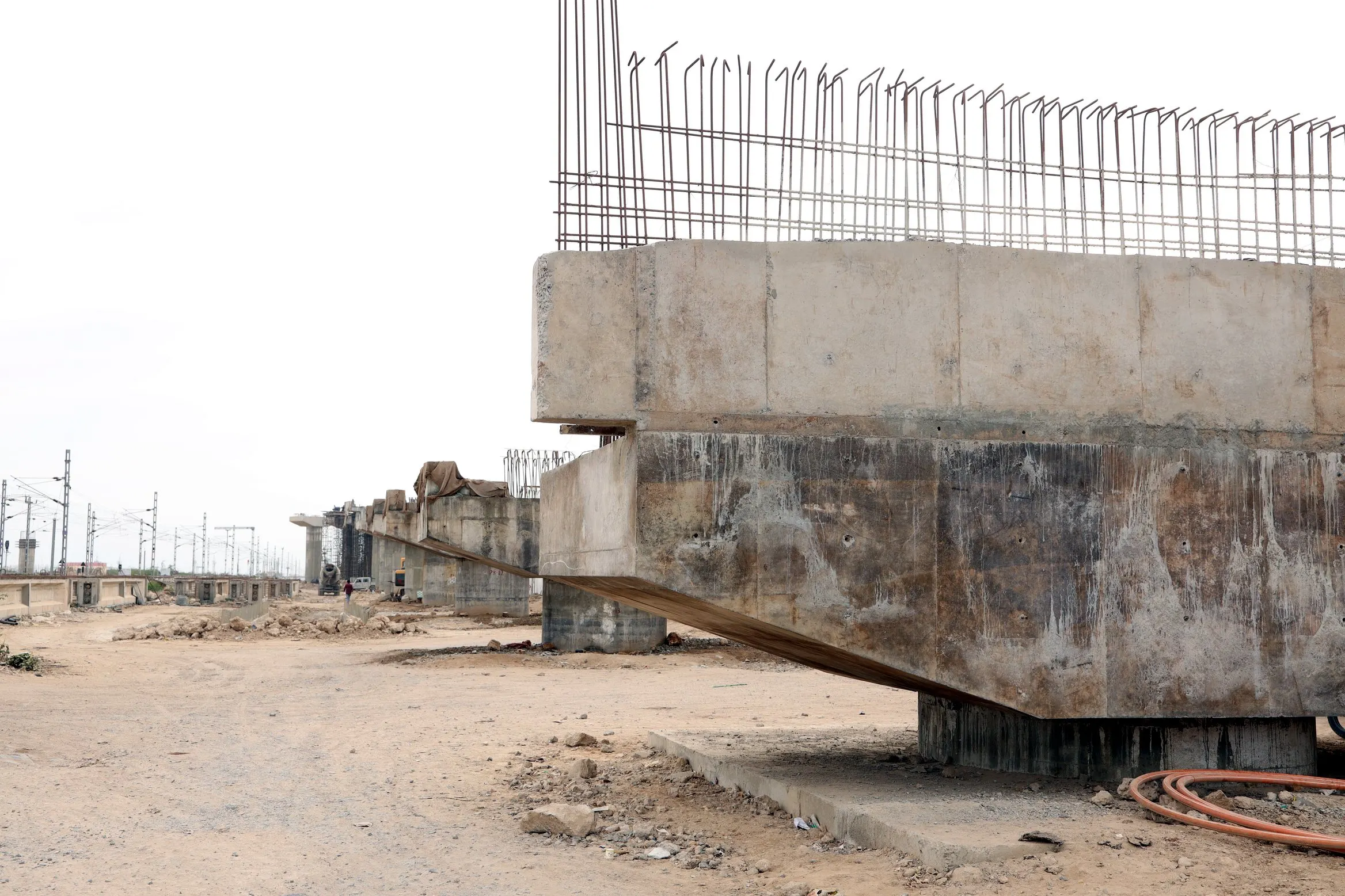
03
Pier cap
The hammerhead on top of the pier that catches the girders.
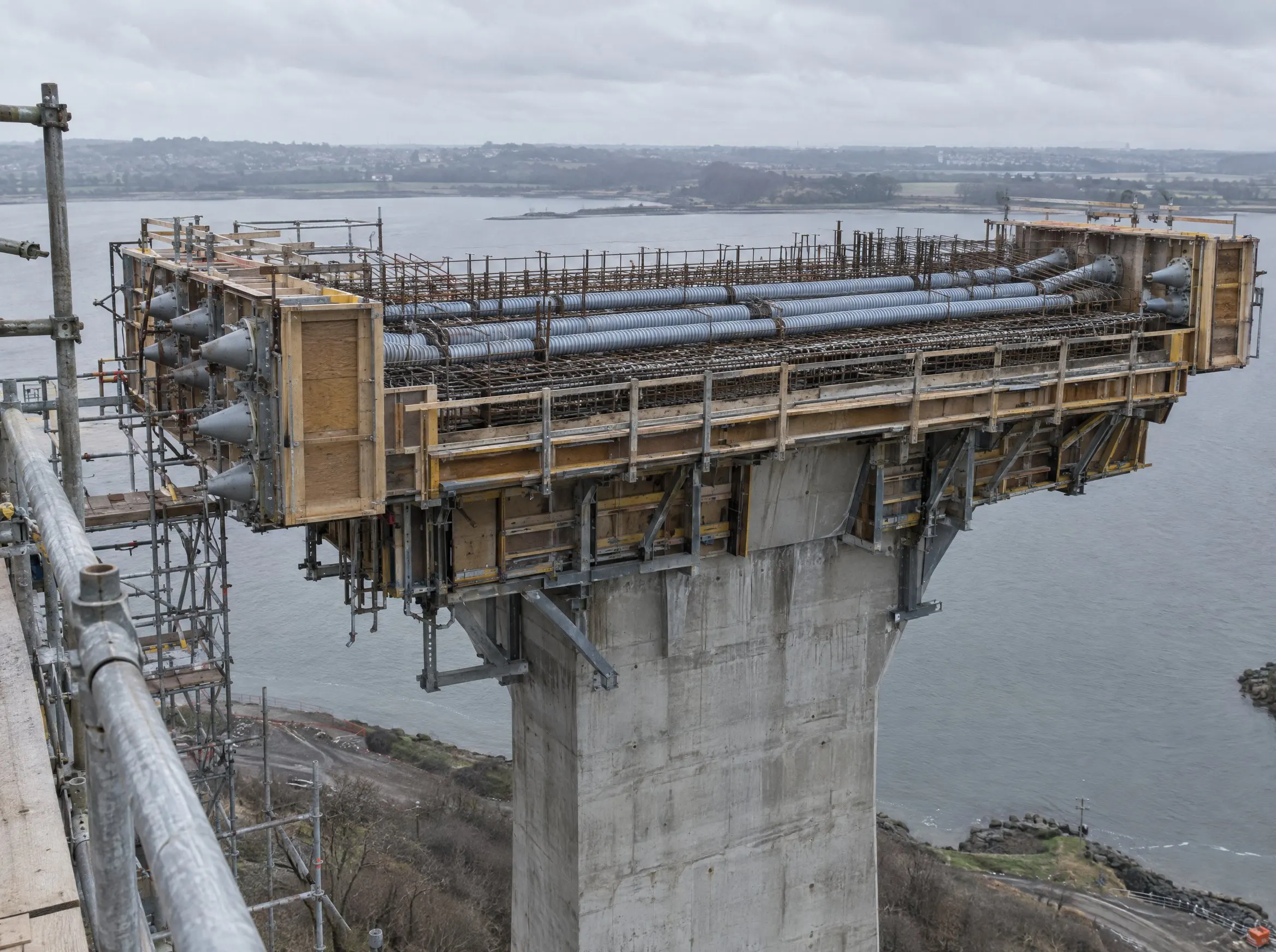
A cantilevered cap spreads the bearings across the deck width. Where it cantilevers far, it is post-tensioned: ducts are cast in, then tendons are stressed from the end faces so the cap stays in compression under the girder loads. The cap pictured stands on the Okha railway bridge in Gujarat, a TYROS stressing site.
- Tendons run straight through the pier, parabolic toward the tips
- Stressed in stages as girders land, often from one end with the other dead
- Typical tendon: 12 to 19 strands of 15.2 mm
TYROS supplies & stressesAT anchorages, HDPE ducts and spirals cast into the cap; TYROS crews thread, stress, check elongation and grout.
04
Bearings
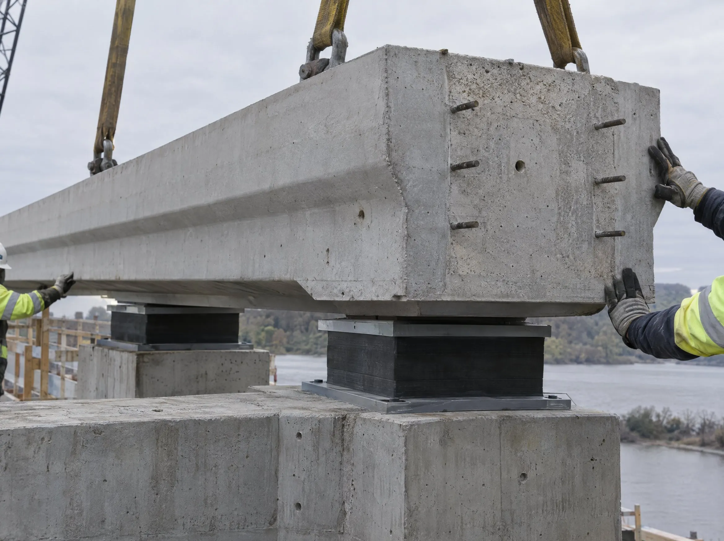
Rubber and steel pads that let the deck move.
Elastomeric or pot bearings sit on pedestals on the pier cap. They carry the vertical load and let the deck expand, contract and rotate without cracking the pier.
- Set level to ±1 mm
- Pedestals grouted after bearing is aligned
- Replaceable over the bridge's life
Other contractors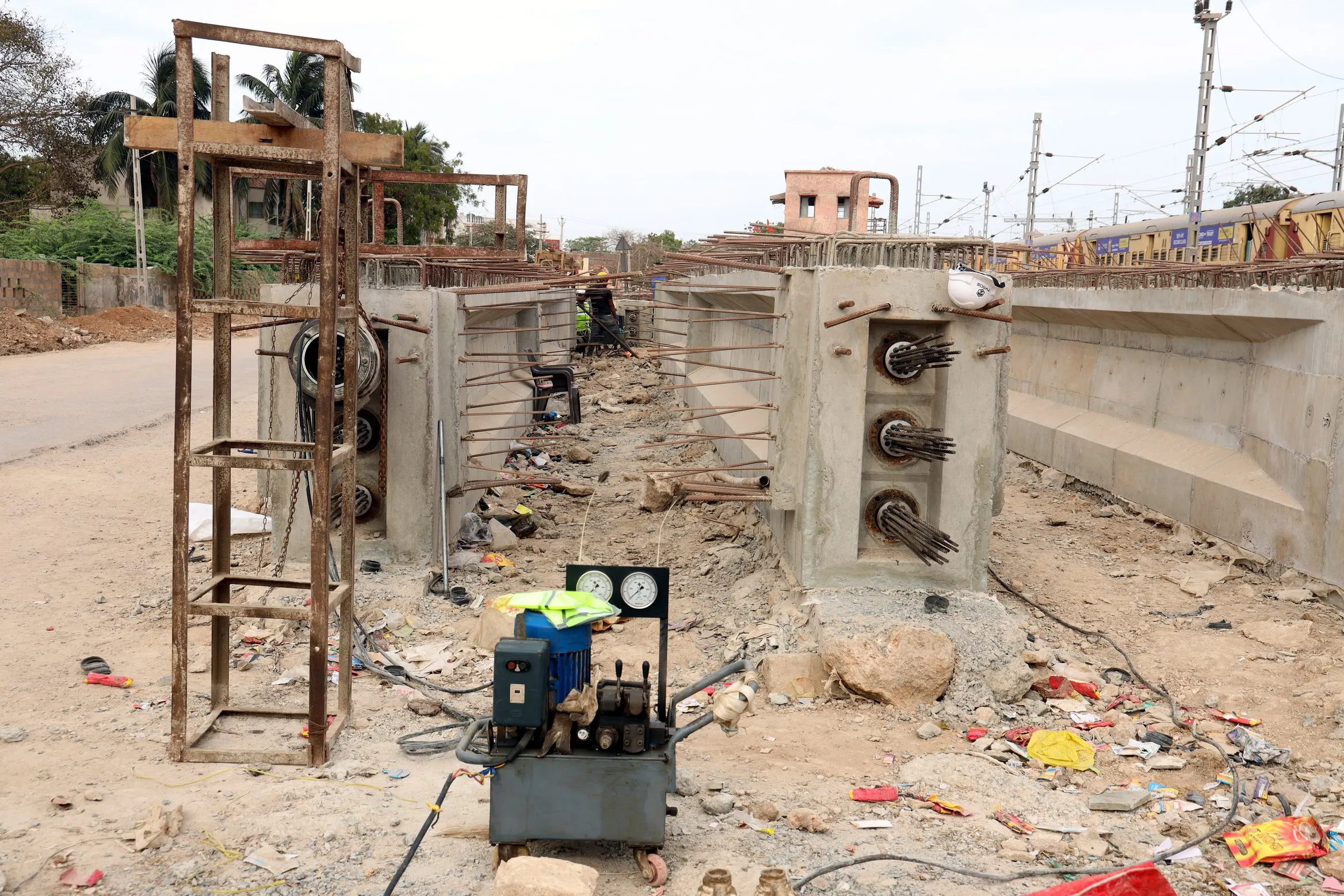
05
Girders
The spans themselves: precast I or U girders, or box segments.
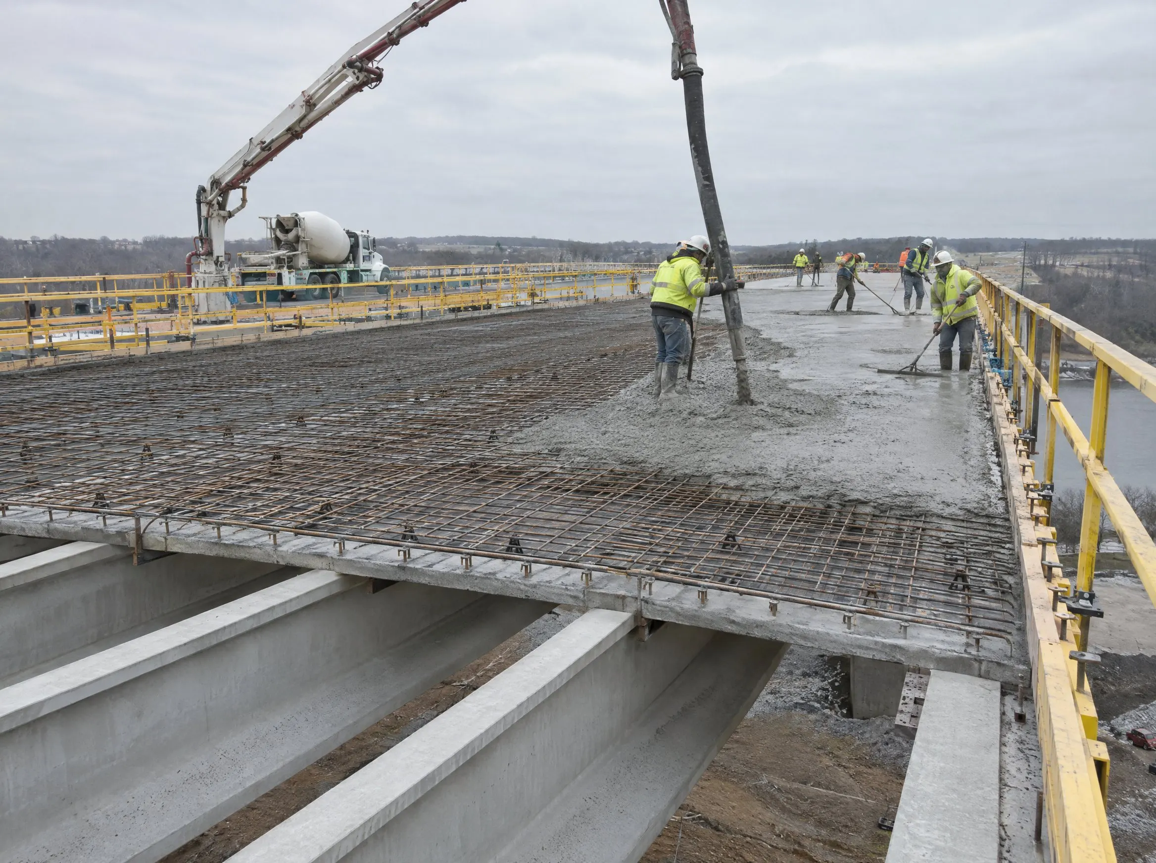
Girders are cast in a yard with ducts and anchorages inside, lifted onto the bearings, then post-tensioned. Stressing lifts the girder off its soffit form and puts the whole section into compression before any traffic load arrives.
- Spans of 25–45 m with precast girders, longer with segmental boxes
- Stressed to 80% of UTS in recorded increments
- Elongation checked against design within ±5%
TYROS supplies & stressesAT heads, cones, wedges, spirals and ducts in every girder; stressing and grouting on the bed or on the pier.
06
Deck slab
The slab that ties the girders into one deck.
A reinforced concrete slab is cast over the girders on stay-in-place or removable forms. Diaphragms between girders are cast at the same time so the span acts as one unit.
- Poured in a set sequence to control cracking
- Cured 7 to 14 days before loading
- Transverse post-tensioning on wide decks
TYROS stressesWhere the deck is transversely prestressed, TYROS stresses and grouts the slab tendons.
07
Finishing
Barriers, joints, waterproofing and the road.
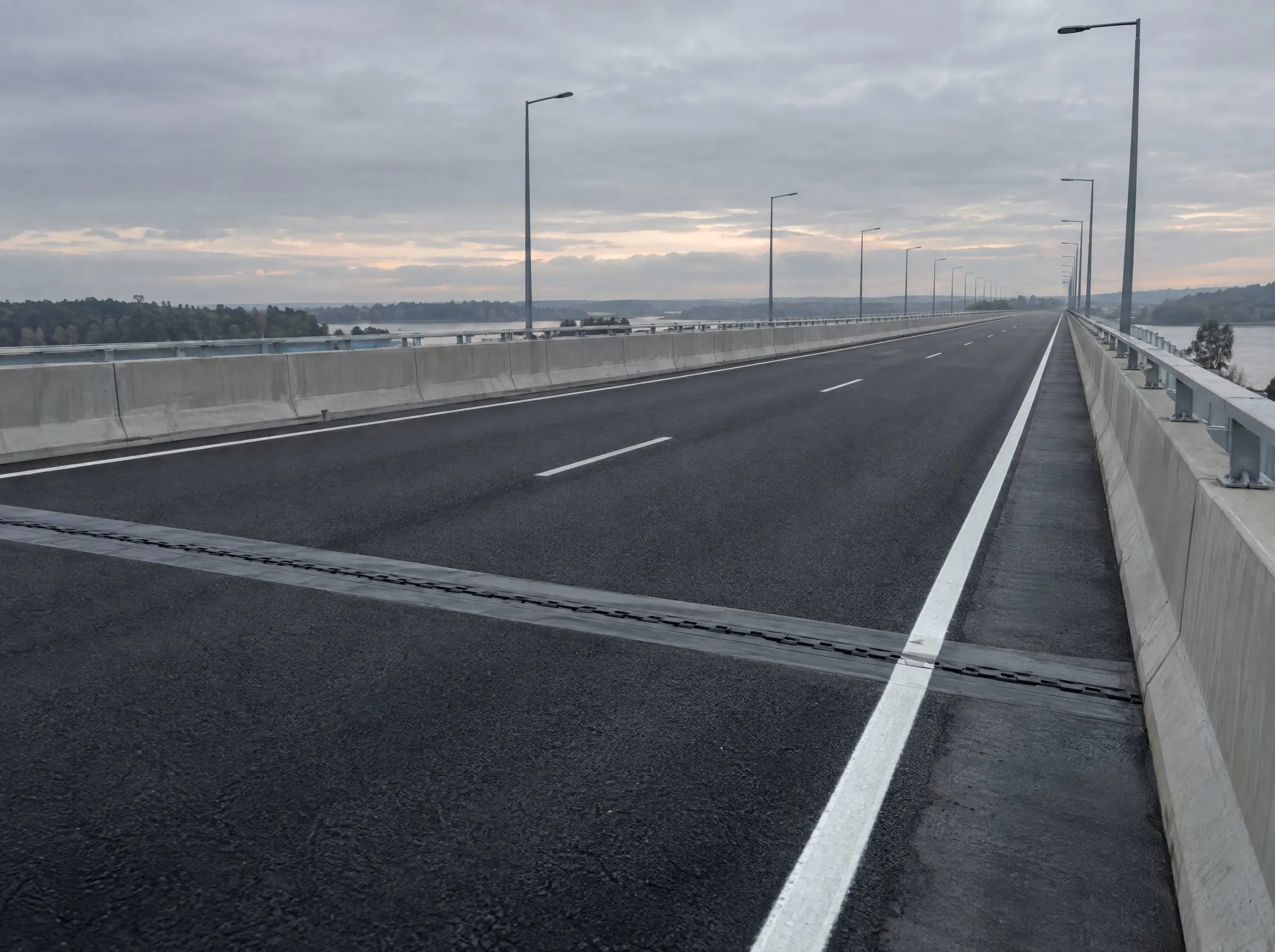
Crash barriers, expansion joints, drainage, waterproofing membrane and the asphalt wearing course go on last. Grouting records and stressing records are handed over with the as-built drawings.
- Expansion joints sized to the deck's thermal movement
- Grout records prove every duct is filled
- Design life 100 years under IRC:112
Other contractors
Stage 01 of 07
Foundations
Why a pier cap gets post-tensioned.
A cantilever pier cap carries two girder lines on each arm. Without prestress the top fibre cracks under that load; tendons draped along the cap keep the whole section in compression and let the cap be shallower and the pier slimmer.
Ducts run the length of the cap: straight through the pier, curving toward the anchorage recesses on the end faces. Tendons are 12 to 19 strands of 15.2 mm in HDPE ducts, anchored with AT heads on square bearing cones.
- 01Cast the cap with ducts, cones, spirals and grout vents in the reinforcement cage
- 02Concrete reaches transfer strength (typically 35 MPa at 7 days)
- 03Thread strands and fit heads and wedges at the live end
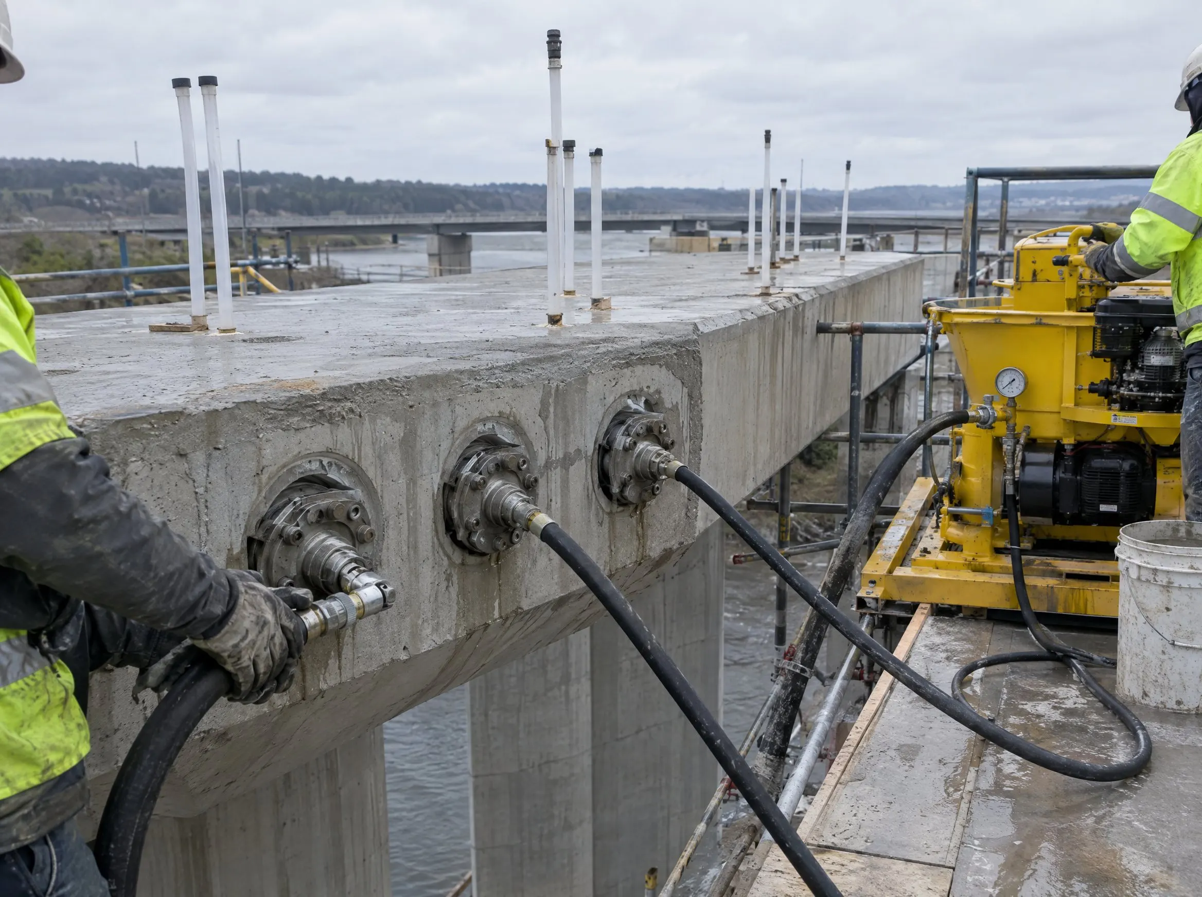
- 04Stress from one end with the far end dead, in stages matched to girder erection
- 05Check elongation, lock off, cut and seal, then grout under pressure
The pier cap pictured is on the Okha railway bridge, Gujarat, a TYROS site.
Pier cap stressing service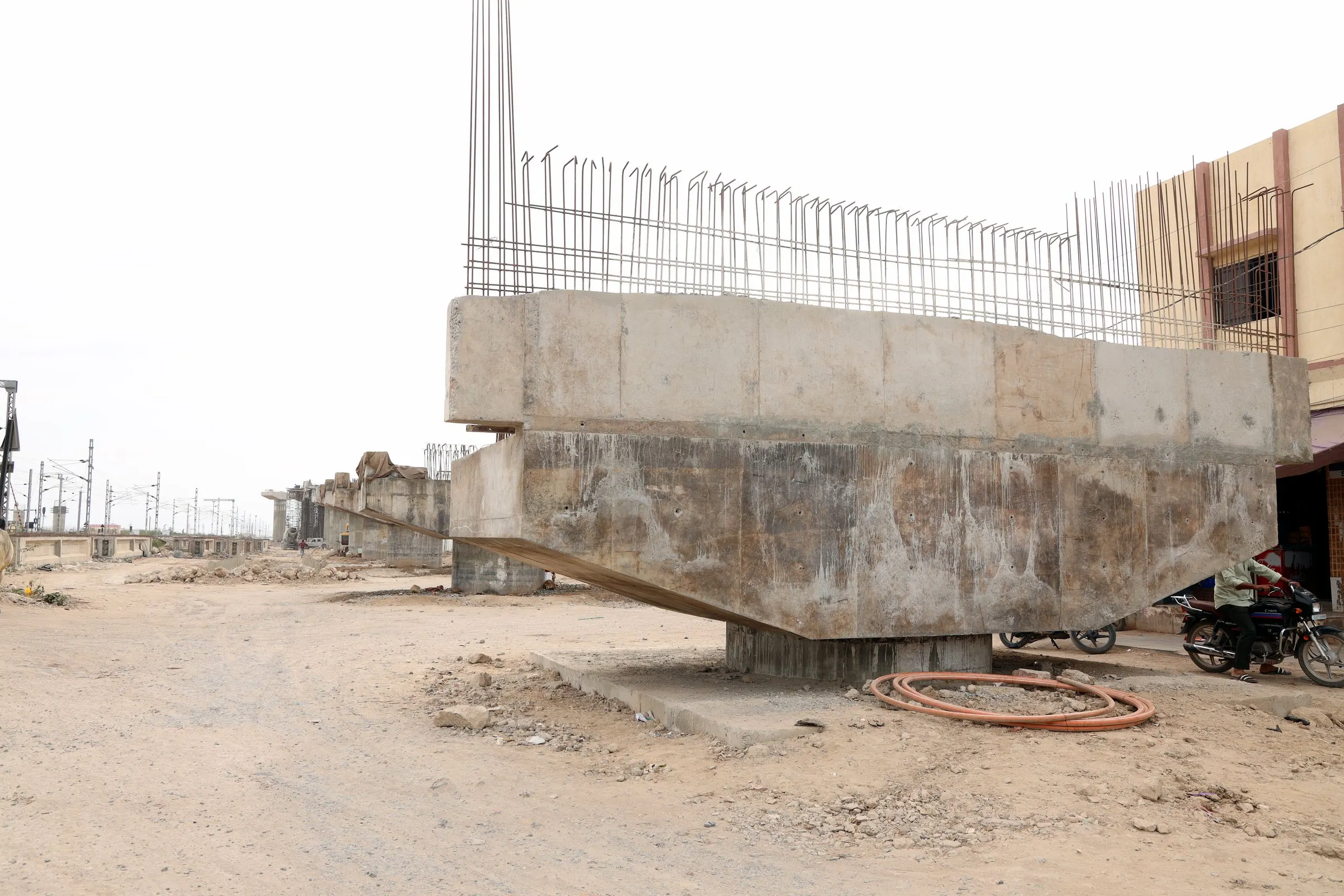
Where TYROS fits.
Products limited to the AT system on this site; services limited to post-tensioning. Nothing else, done properly.
03 · Pier cap
AT anchorages, HDPE ducts and spirals cast into the cap; TYROS crews thread, stress, check elongation and grout.
05 · Girders
AT heads, cones, wedges, spirals and ducts in every girder; stressing and grouting on the bed or on the pier.
06 · Deck slab
Where the deck is transversely prestressed, TYROS stresses and grouts the slab tendons.
Send us the tendon schedule. We'll send back the anchorage.
Anchorage specifications, anti-burst reinforcement details and the stressing methodology — for every contractor, on every job.
Need the tendons stressed too? See our post-tensioning stressing services.